Posi-Lock PSL-G-32
Model PSL-G-32 / PSL-G-32-C / PSL-G / Miki Pulley (Official website) / Listed on page 5 of the document
Friction joint that clamps a shaft and hub by frictional force. Tightened with clamping bolts.
Last verified: (date the content was verified against the source document)
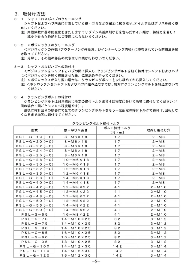
A reduced image of the relevant page is quoted from the document. Copyright belongs to Miki Pulley.Request removal
Specifications
| Clamping bolt | 12-M6×18 |
|---|---|
| Clamping bolt tightening torque | 17 N・m |
| Removal screw hole | 2-M8 |
PSL-G model comparison
Compare 28 models in the same series by specification.
| Model | Clamping bolt | Clamping bolt tightening torque | Removal screw hole |
|---|---|---|---|
| POSI LOCK PSL-G | — | — | — |
| PSL-G-100 | 14-M12×30 | 142 N・m | 3-M14 |
| PSL-G-110 | 14-M12×30 | 142 N・m | 3-M14 |
| PSL-G-120 | 16-M12×30 | 142 N・m | 3-M14 |
| PSL-G-19 / PSL-G-19-C | 8-M6×18 | 17 N・m | 2-M8 |
| PSL-G-20 / PSL-G-20-C | 8-M6×18 | 17 N・m | 2-M8 |
| PSL-G-22 / PSL-G-22-C | 8-M6×18 | 17 N・m | 2-M8 |
| PSL-G-24 / PSL-G-24-C | 8-M6×18 | 17 N・m | 2-M8 |
| PSL-G-25 / PSL-G-25-C | 8-M6×18 | 17 N・m | 2-M8 |
| PSL-G-28 / PSL-G-28-C | 10-M6×18 | 17 N・m | 2-M8 |
| PSL-G-30 / PSL-G-30-C | 10-M6×18 | 17 N・m | 2-M8 |
| PSL-G-32 / PSL-G-32-C This product | 12-M6×18 | 17 N・m | 2-M8 |
| PSL-G-35 / PSL-G-35-C | 12-M6×18 | 17 N・m | 2-M8 |
| PSL-G-38 / PSL-G-38-C | 14-M6×18 | 17 N・m | 2-M8 |
| PSL-G-40 / PSL-G-40-C | 14-M6×18 | 17 N・m | 2-M8 |
| PSL-G-42 / PSL-G-42-C | 12-M8×22 | 41 N・m | 2-M10 |
| PSL-G-45 / PSL-G-45-C | 12-M8×22 | 41 N・m | 2-M10 |
| PSL-G-48 / PSL-G-48-C | 12-M8×22 | 41 N・m | 2-M10 |
| PSL-G-50 / PSL-G-50-C | 12-M8×22 | 41 N・m | 2-M10 |
| PSL-G-55 / PSL-G-55-C | 14-M8×22 | 41 N・m | 2-M10 |
| PSL-G-60 / PSL-G-60-C | 14-M8×22 | 41 N・m | 2-M10 |
| PSL-G-65 | 16-M8×22 | 41 N・m | 2-M10 |
| PSL-G-70 | 14-M10×25 | 82 N・m | 3-M12 |
| PSL-G-75 | 14-M10×25 | 82 N・m | 3-M12 |
| PSL-G-80 | 14-M10×25 | 82 N・m | 3-M12 |
| PSL-G-85 | 16-M10×25 | 82 N・m | 3-M12 |
| PSL-G-90 | 16-M10×25 | 82 N・m | 3-M12 |
| PSL-G-95 | 18-M10×25 | 82 N・m | 3-M12 |
How to choose Friction joint
Points to check when selecting, with the values for this product (PSL-G-32 / PSL-G-32-C).
-
1. Match the Shaft Diameter and Boss Bore Diameter
The applicable shaft diameter d is the outer diameter of the shaft to be installed, and the outer diameter D is the dimension that fits into the boss bore. Friction fastening depends on controlling the fit clearance, so also confirm that the shaft and boss bore can be machined to the manufacturer's specified tolerances and surface roughness.
-
2. Allow a Margin in Allowable Transmission Torque
If the allowable transmission torque T is exceeded, the fastening surfaces slip, causing misalignment and wear. Select based not only on the motor's rated torque but also on the peak torque during startup or impact loads multiplied by a service factor.
-
3. Check Simultaneous Action with Thrust Force
For applications with axial loads, check the allowable thrust force. When torque and thrust force act simultaneously, they share the friction force, so each allowable value may not be usable independently; confirm the manufacturer's handling of combined loads.
-
4. Examine Boss Strength from Side Pressure on the Boss
During fastening, surface pressure acts on the inner surface of the boss, which pushes it outward. Calculate the required boss outer diameter and wall thickness from the boss side pressure and the yield point of the boss material, and for thin-walled bosses or low-strength materials such as aluminum, check for breakage or deformation. Examine the shaft side in the same way using the shaft side pressure.
-
5. Review the Relationship Between Overall Length and Boss Width
The overall length L is the axial fastening length. If the boss width is shorter than this, the fastening surface is insufficient and the performance will not be achieved. Together with the installation space, confirm that the boss width satisfies the overall length and that working space for bolt heads and tools is secured.
-
6. Tighten Evenly to the Specified Tightening Torque
This product: Clamping bolt tightening torque 17 N・mBecause transmission performance depends on the clamping force of the clamping bolts, control the tightening torque (1 to 142 N·m for the listed products) with a torque wrench, and tighten evenly in several passes following a diagonal sequence. Also confirm in advance the required tool size and how to use the removal screw holes.
This guide was written by AI based on the listed products' documents and specification items.
Description
Consists of five components: front taper ring, outer ring, inner ring, rear taper ring, and clamping bolts. Clamps the shaft and hub by frictional force.
Features
- Delivers high transmission torque through frictional clamping
- Enables easy and accurate positioning
- Clamping is released by loosening the clamping bolts
Applications
- Clamping of shafts and hubs
- Positioning
FAQ
- Q. How does the PSL-G-32 clamp a shaft and hub?
- A. It is a friction joint that clamps a shaft and hub by frictional force. It consists of five components: front taper ring, outer ring, inner ring, rear taper ring, and clamping bolts, and is tightened with the clamping bolts.
- Q. What are the tightening torque and removal screw hole of the PSL-G-32 clamping bolts?
- A. The clamping bolts are 12-M6×18, and the tightening torque is 17 N・m. The removal screw holes are 2-M8.
- Q. What applications is the PSL-G-32 suited for?
- A. It can be used for clamping and positioning shafts and hubs. It enables easy and accurate positioning.
- Q. Can the clamping of the PSL-G-32 be released?
- A. Yes, clamping is released by loosening the clamping bolts.
Written by AI based on the content of the source documents.
Source documents
- Manual ポジロック PSL-G / PSL-G-C 取扱説明書 6 pages Open page 5
Similar products (other manufacturers)
Friction joint products, ordered by similarity of specifications and applications.
-
Drive shaft
Drive Shaft for Rolling Mills (Block Type)
A high-strength, long-life drive shaft that drives rolls in rolling mills. Used under demanding conditions such as plate rolling mills and hot rolling mills.
JTEKT Corporation
-
Torque limiter
Hyper Coupling (Torque Limiter)
A torque limiter that protects rolling mill drive systems from excessive torque. Improves operating accuracy and durability, and shortens recovery time.
JTEKT Corporation
-
Chain
Ultra Super Chain RF100-US-1
Model: RF100-US-1
Heavy-duty drive chain with 31.75 mm pitch. Minimum tensile strength 149 kN, maximum allowable tension 39.2 kN.
Tsubakimoto Chain Co.
-
Chain
Ultra Super Chain RF120-US-1
Model: RF120-US-1
High-strength drive chain with 38.10 mm pitch. Minimum tensile strength 213 kN, maximum allowable tension 53.9 kN.
Tsubakimoto Chain Co.
More products from Miki Pulley
See all →-
Friction joint
Posi-Lock PSL-D
Friction joint that clamps a shaft and hub together by frictional force. Tightening the clamping bolts evenly to the specified torque provides high transmission torque and accurate positioning. Sizes range from model 6 to 50.
Miki Pulley
-
Friction joint
Posi-Lock PSL-D-C (Simple Anti-Corrosion Specification)
Simple anti-corrosion specification version of the PSL-D. The body is electroless nickel plated, and the clamping bolts are treated with Geomet coating to enhance corrosion resistance. Available from size 16 and above.
Miki Pulley
-
Friction joint
Posilock PSL-G-19
Model: PSL-G-19 / PSL-G-19-C
Friction joint that fastens a shaft and hub by frictional force. Tightened with clamping bolts.
Miki Pulley
-
Friction joint
Posilock PSL-G-20
Model: PSL-G-20 / PSL-G-20-C
Friction joint that clamps shaft and hub together by frictional force. Tightened with clamping bolts.
Miki Pulley
-
Friction joint
POSILOCK PSL-G-22
Model: PSL-G-22 / PSL-G-22-C
A friction joint that clamps a shaft and hub together by friction force. Tightened with clamping bolts.
Miki Pulley
-
Friction joint
POSILOCK PSL-G-24
Model: PSL-G-24 / PSL-G-24-C
Friction joint that clamps a shaft and hub by friction force, tightened with clamping bolts.
Miki Pulley